Load & feed
Position angle stock on the feeding track and select the job information.

Program the holes. Feed the angle. Punch and cut to length.
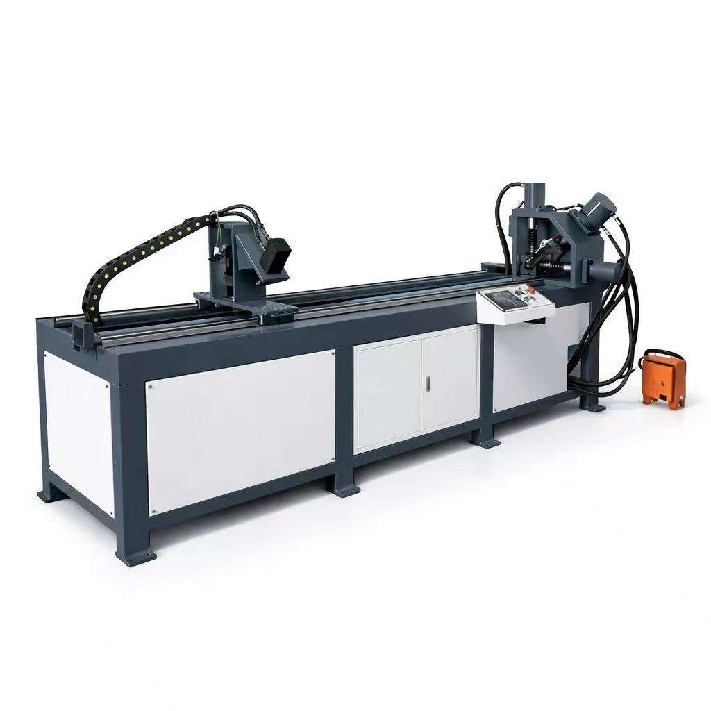
Prepare angle-steel members for duct flange frames in a controlled feeding, punching and hydraulic cutting workflow. The reference material size range is 30–50 mm, with angle lengths up to 6 m.
Send your angle section, hole drawing and required cut lengths for a configuration quotation.
Plan the sequence around the required member lengths and fixing holes. Corner joining and flange frame assembly are separate workshop operations.
Position angle stock on the feeding track and select the job information.
Advance the material to the programmed hole and cutting positions.
Create fixing holes with tooling matched to the angle section and drawing.
Cut the required member lengths and collect them for frame assembly.
The reference specification lists keyboard / USB input and CAD input. Define dimensions, hole arrangement and quantities before processing. Confirm the supported drawing format with the selected configuration.
Plan access for stock loading, feeding and part collection. Allow for 6 m angle lengths and the separate handling, joining and assembly operations.
A separate angle-steel frame surrounds a duct opening. Its fixing holes are used when connecting the mating duct sections.
Specify the angle section and thickness, frame dimensions, hole diameter and spacing, corner joining method and required quantities. These details help match the line to your flange work.
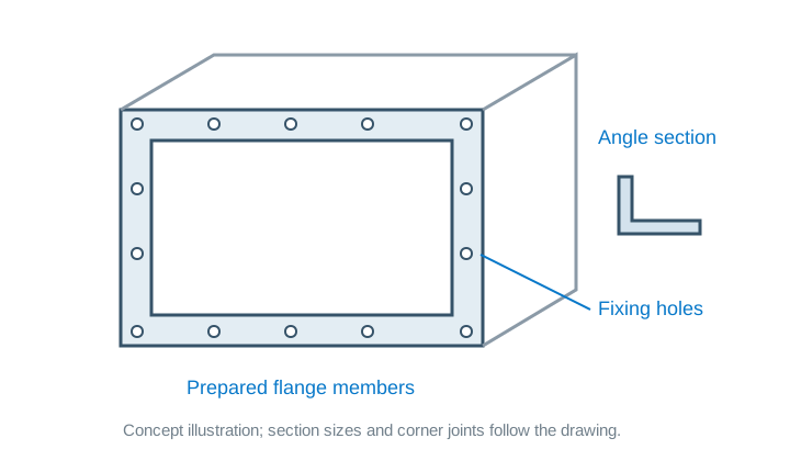
Provide section size, material grade and thickness. Match the punching and cutting tooling to the required angle profile.
Provide hole spacing, end distances and cut lengths. Include repeated parts and mixed production batches.
The reference lists four axes and right-to-left working direction. Confirm job input, power supply and material access for the line.
| Parameter | Value | Unit |
|---|---|---|
| Material size range | 30–50 | mm |
| Maximum diameter | 26 | |
| Punching pressure | 400 | |
| Dies quantity | 1 | |
| Maximum angle length | 6 | m |
| Maximum cutting length | 6 | m |
| Cutting system | Hydraulic | |
| Working speed | 1000 | |
| Accuracy reference | GB2694-2003 | |
| Feeding speed | 15 | |
| Program input | Keyboard / USB input; CAD input | |
| Working direction | Right to left | |
| Axes | 4 |
It combines controlled feeding, hole punching and hydraulic cutting to prepare angle-steel flange members.
The described line prepares the members. Corner joining, welding where required and frame assembly are separate operations.
Send the angle section size, material grade and thickness, hole drawing, end distances and cut lengths. The reference lists one die set; discuss tooling for your section sizes when requesting a quote.
The specification lists keyboard / USB and CAD input. Confirm the accepted file format and programming procedure with the selected configuration.
Provide your angle section, hole pattern, longest stock and cut lengths, quantities, electrical supply and destination country. A drawing of the flange members is especially useful.
Send the section size, hole drawing and production requirements so we can discuss a suitable configuration.