
Bend Radius & Wall Thickness
Published · Updated
Read centerline radius, outside diameter and wall thickness together. They help describe the bending difficulty; they are not universal minimum-radius or mandrel rules.
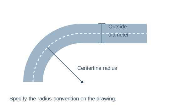
Use the same radius convention on every drawing
Centerline radius: CLR
State the centerline radius explicitly. Do not send an inside-radius value under a centerline label: that changes the geometry the supplier is asked to produce.
For ideal circular geometry, inside radius = CLR − OD/2 and outside radius = CLR + OD/2. These relationships interpret the drawing, not wall thinning or a machine capacity.
Actual OD and wall
Use measured or specified actual dimensions and material grade. Nominal pipe size is not the outside diameter used to calculate the geometric relationship.
Include wall variation and finished-quality requirements. Tool fit and support must be reviewed for the actual section.
A transparent arithmetic example
OD 40 mm · wall 2 mm · CLR 80 mm
These invented example inputs explain the calculations. They are not WinYing capacity data, a minimum bend recommendation or acceptance criteria.
Ideal inside radius = 80 − 20 = 60 mm. Ideal outside radius = 80 + 20 = 100 mm.
80 / 40 describes radius relative to tube diameter.
40 / 2 describes relative wall thinness.
The ratios communicate geometry. Material, tooling, support and required deformation limits still determine whether the part is acceptable. No pass/fail threshold follows from this example.
Inspect the outcomes the support must control
Flattening / ovality
Define the permitted section change and how it is measured. Inspect the difficult bend in the finished part rather than relying on machine motion values.
Wrinkling / wall condition
Review grade, wall, radius and supporting tools together. A tool arrangement suited to one tube batch or geometry may need review when those inputs change.
Surface marks / appearance
State cosmetic and functional surface criteria. Inspect tool contact areas and the required finish using the quoted stock.
Tooling is an application decision
Inspect flattening/ovality, wrinkling, wall changes and surface marks according to the part specification. The same tube size can behave differently with grade, temper, seam condition and surface finish.
Ask whether the bend die, clamp, pressure support, mandrel and wiper arrangement are appropriate. Do not assume every machine includes every supporting tool. Changes to wall or radius can require different setup even when the outside diameter remains unchanged.
Ask what is included
Confirm the bend die, clamp, pressure support and any mandrel/wiper arrangement. Specify every required size/radius and the setup/changeover scope.
Show the whole part
Short straights and adjacent bends affect clamping, support and clearance. A local radius test does not prove the complete sequence can be executed.
Maximum listed radius does not answer the minimum-radius question
The DW38NC reference lists maximum R190 and describes minimum radius as dependent on diameter. The DW-38CNC lists maximum R180. Neither figure establishes the minimum feasible radius for your material.
Also show short straight lengths and adjacent bends. Clamp access, tool clearance and collision with the already formed part can limit the full sequence. Review complete bender selection rather than testing only an isolated bend.
| Reference | Listed entry | Still needs confirmation |
|---|---|---|
| DW38NC | Maximum R190; minimum depends on diameter | Actual grade / wall / tooling minimum |
| DW-38CNC | Maximum R180 | Actual grade / wall / tooling minimum |
| Any completed multi-bend part | Straight lengths and rotations on drawing | Clamping, support and collision clearance |
Scroll the comparison table horizontally to see every column.
Keep the accepted setup tied to the stock
- 01Define
Agree dimensions, grade and radius convention.
- 02Tool
Confirm die and support arrangement.
- 03Make
Produce the complete representative part.
- 04Measure
Check geometry and permitted deformation.
- 05Repeat
Record the approved setup and stock details.
If grade, wall, radius or surface requirement changes, review the accepted process again. A record of one successful job is useful evidence for that job, not a blanket approval of every similar tube.
Send geometry and quality criteria together
WinYing Machinery can review the stock, drawing and support needs before discussing a bender configuration. Keep radius terminology and finished acceptance limits unambiguous.
Discuss this application →- 01Actual OD, wall and grade
- 02Centerline radii and complete sequence
- 03Ovality, appearance and dimension criteria
- 04Tooling review and repeat production needs
Frequently Asked Questions
Is inside radius the same as centerline radius?
No. For circular geometry they differ by half the OD. State the convention clearly.
Does R190 mean a minimum radius?
No. In the cited DW38NC table it is a maximum radius; minimum feasibility needs confirmation.
Does thin wall always need a mandrel?
Support requirements depend on the complete application and quality criteria. Obtain tooling review.
Are CLR/OD ratios acceptance rules?
No. They describe geometry; they do not establish a universal machine or quality threshold.
Should a new stock grade use the same accepted setup automatically?
No. Review changed material, wall and surface requirements against tooling and the finished-quality trial before treating the setup as approved.