
NC Hydraulic Pipe Bending Machine
Choose a DW NC hydraulic bender from material, OD–wall pair, radius and complete workpiece. Confirm the operator and machine responsibilities for each movement.
- Models
- DW38NC–DW219NC
- Control route
- NC hydraulic
- Source max pressure
- 14 MPa
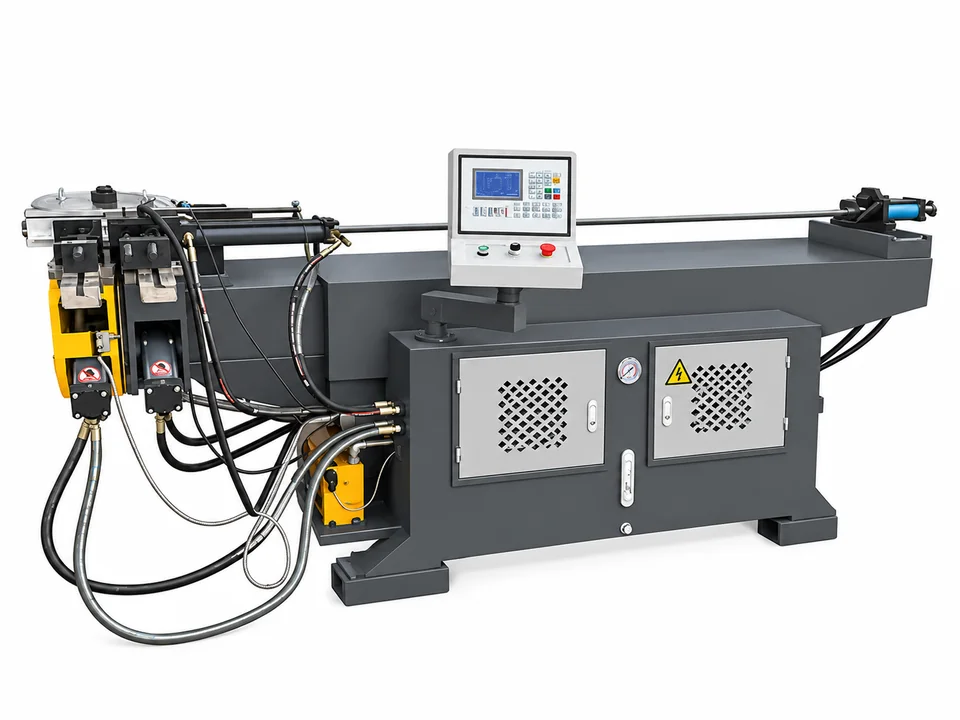
Shortlist a DW model using the actual OD–wall pair
| Model | Capacity reference | Max radius / mandrel-distance reference |
|---|---|---|
| DW38NC | Φ38×2 | R190 / 1600 mm |
| DW63NC | Φ63×4 | R300 / 2600 mm |
| DW130NC | Φ130×8 | R600 / 4500 mm |
| DW219NC | Φ219×16 | R700 / 5000 mm |
NC settings and operator actions must be separated
Ask which movement is controlled
The source identifies NC control and hydraulic bending. Confirm how tube feeding, rotation, clamping and the bend sequence are handled on the quoted model.
Stored sections or multiple bends do not by themselves prove servo feed and turning. For recurring multi-bend parts, review each position and operator action using the complete drawing.
Mandrel distance and tooling scope
Distance reference
The table’s Max. Effective Mandrel Distance is a source machine dimension. Confirm how it applies to the actual tube, usable workpiece and support arrangement.
Tube support
Specify the required inside and outside bend condition. Confirm whether mandrel, wiper or other support tooling is required and included.
Part access
Show straight lengths, bend spacing and rotation planes. Review clamping and collision clearance before approving the sequence.
Complete DW38NC–DW219NC Source Table
Open the complete supplied model table
| Model | Max. Bending Capability | Max. Bending Radius | Min. Bending Radius | Max. Bending Degree | Max. Effective Mandrel Distance (mm) | Control | Max. Elbow Bend Pipe | Max. Storable Sections | Motor Power (kW) | Max. Hydraulic Pressure (MPa) | Hydraulic System Control | Oil Tank (L) | Measurement (mm) | Weight (kg) |
|---|---|---|---|---|---|---|---|---|---|---|---|---|---|---|
| DW38NC | Φ38×2 | R190 | According to diameter | 190 | 1600 | NC Control | 16 | 16×16 | 5.5 | 14 | Electromagnetic valve | 180 | 2800×800×1300 | 800 |
| DW50NC | Φ50×2 | R250 | According to diameter | 190 | 2200 | NC Control | 16 | 16×16 | 5.5 | 14 | Electromagnetic valve | 200 | 3400×850×1400 | 1200 |
| DW63NC | Φ63×4 | R300 | According to diameter | 190 | 2600 | NC Control | 16 | 16×16 | 7.5 | 14 | Electromagnetic valve | 260 | 3600×900×1450 | 1800 |
| DW75NC | Φ75×5 | R400 | According to diameter | 190 | 3300 | NC Control | 16 | 16×16 | 7.5 | 14 | Electromagnetic valve | 290 | 4400×1000×1500 | 2200 |
| DW89NC | Φ89×6 | R450 | According to diameter | 190 | 3300 | NC Control | 16 | 16×16 | 11 | 14 | Electromagnetic valve | 290 | 4400×1050×1550 | 3500 |
| DW100NC | Φ100×6 | R450 | According to diameter | 190 | 3200 | NC Control | 16 | 16×16 | 11 | 14 | Electromagnetic valve | 290 | 4550×1050×1550 | 4000 |
| DW115NC | Φ115×8 | R500 | According to diameter | 190 | 4500 | NC Control | 16 | 16×16 | 18.5 | 14 | Electromagnetic valve | 550 | 6800×1600×1800 | 7500 |
| DW130NC | Φ130×8 | R600 | According to diameter | 190 | 4500 | NC Control | 16 | 16×16 | 18.5 | 14 | Electromagnetic valve | 550 | 6800×1650×1800 | 8000 |
| DW168NC | Φ168×12 | R650 | According to diameter | 190 | 4800 | NC Control | 16 | 16×16 | 30+18.5 | 14 | Electromagnetic valve | 800 | 7500×2000×2000 | 13000 |
| DW219NC | Φ219×16 | R700 | According to diameter | 190 | 5000 | NC Control | 16 | 16×16 | 37+22 | 14 | Electromagnetic valve | 800 | 7800×2300×2250 | 38000 |
Keep the actual model row as the quotation reference. The 16 and 16×16 storage-related entries need the supplier’s definition; do not reinterpret them as CNC axis counts. Paired motor powers such as 30+18.5 and 37+22 kW retain their source notation and require the complete utility schedule.
NC or CNC for the recurring part?
| Review item | DW NC page | DW CNC page |
|---|---|---|
| Bend controls | NC hydraulic description | Programmable bending description |
| Tube feed / turn | Confirm actual operator and machine functions | Servo feed and turning described; confirm quoted package |
| Part acceptance | Complete drawing and sample | Complete drawing and programmed sample |
| Production comparison | Include positioning and handling | Include setup, loading and changeovers |
Agree an industrial trial and installation brief
- Tube and sampleGrade, OD, wall, seam/finish and the most demanding complete part.
- Quality criteriaFinished dimensions, angles, shape and accepted deformation.
- Utilities and layoutThe source lists maximum hydraulic pressure 14 MPa; confirm operating requirements, electrical supply and handling space.
- Acceptance cycleRecord settings, operator actions and the accepted repeated part.
Questions to settle before ordering
Is the minimum radius specified numerically?
No. The table says According to diameter. Confirm tooling and actual material for the required radius.
Does NC include automatic feeding and turning?
The table does not establish those functions. Confirm each motion and operator action for the quoted model.
Is the maximum mandrel distance a finished tube-length guarantee?
No. Review its definition, loading and support against the actual part.
Does a distance entry confirm included mandrel tooling?
No. Agree support tooling and inclusion separately.
What should WinYing review before quotation?
Actual grade, OD, wall, radius, complete bend sequence, quality criteria and site requirements.
Tell Us Your Hydraulic Tube Bending Requirements
Send tube material, outside diameter, wall thickness, bending radius, workpiece length and drawing so we can confirm the suitable DW model and tooling.