
NC vs CNC Pipe Bending Machines
Published · Updated
Ask which motion the machine controls and which motion the operator performs. Then test the complete part: a control label does not remove tooling, clamping or collision constraints.
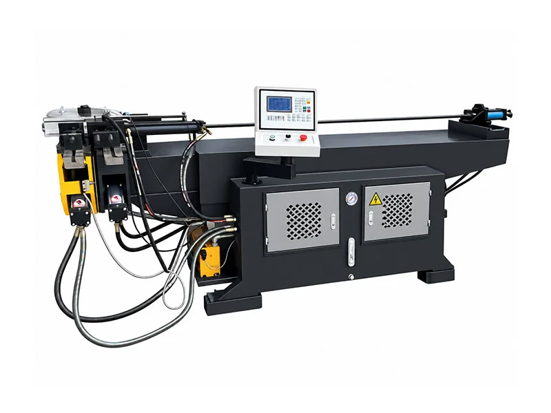
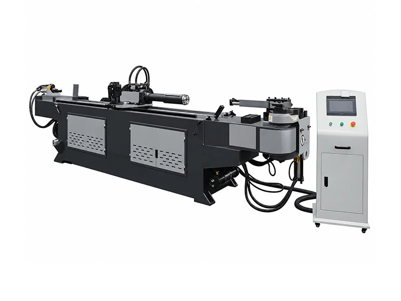
Three movements define the automation discussion
Bend
Set and execute the required bending angle.
Turn
Orient the tube between bends in different planes.
Feed
Locate the next bend along the prepared tube.
On an NC configuration, selected bending settings can be programmed while positioning or rotation may remain operator-dependent. Ask which movements are controlled on the exact quoted machine. Multiple stored bends do not by themselves prove servo feeding and turning.
The DW CNC reference describes programmed bending with servo-controlled turning and feeding, using X/Y/Z or Y/B/C data-entry modes. Confirm actual axes, clamping sequence and direct/indirect feed arrangement. Loading, unloading and setup can still need operator involvement.
The two workflows place responsibility in different places
NC: verify operator-dependent movements
List every required bend, position and rotation. Ask which are programmed and which rely on operator handling, gauges or references. Stored bend counts do not by themselves prove servo feeding or turning.
For recurring simple bends, assess setup, gauging and inspection effort with the intended operator. The NC proposal must still produce the complete accepted part.
CNC: verify the programmed sequence
The DW CNC reference describes servo-controlled turning and feeding with coordinate or workpiece data-entry modes. Confirm actual controlled axes, clamping and direct/indirect feeding.
Automatic bend/turn/feed does not mean automatic loading and unloading. Multi-radius arrangements and additional functions need separate confirmation.
Comparable rows can contain different kinds of dimensions
| Item | DW38NC reference | DW-38CNC reference |
|---|---|---|
| Maximum capability | Φ38×2 | Φ38×2 |
| Maximum radius | R190 | R180 |
| Maximum bend | 190° | 190° |
| Length entry | 1600 mm effective mandrel distance | 2200 mm feeding length |
| Control review | Confirm operator positioning/turning | Servo turning and feeding described |
| Quality acceptance | Completed part measurements | Completed part measurements |
Scroll the comparison table horizontally to see every column.
Two part patterns make the control choice clearer
Repeat bends in one plane
An NC route may be practical if the operator can position consistently and the complete drawing suits the tools. Demonstrate repeated settings, loading and inspection—not only one bend.
Program complexity alone should not decide the purchase. Count accepted parts and the actual handling arrangements.
Multiple bends with repeated rotations
Programmed feed and turn can help recurring frame or routing parts. Demonstrate program creation/recall, the shortest straight and the final orientation after all bends.
Review the growing part for collisions. A successful first bend is not proof that the machine can execute the full sequence.
The same tooling questions apply at either control level
Confirm bend die, clamp, pressure support and any mandrel/wiper arrangement for the actual grade, OD, wall and radius. Ask which tooling is supplied and how many sizes/radii are covered. A diameter-capacity row does not define every thin-wall or tight-radius application.
Read the radius/wall guide and submit the whole bend sequence, not an isolated elbow sketch.
| Input | Why it matters | Confirm in supply scope |
|---|---|---|
| Tube grade, OD and wall | Capacity and forming behavior | Application-specific rating |
| Radius and bend sequence | Dies and changeovers | Included sizes / radii |
| Short straights | Clamp and feed access | Feasible holding arrangement |
| Thin wall / tight geometry | Support and deformation | Mandrel / wiper requirements |
| Finished envelope | Frame and tool clearance | Complete-part trial |
Scroll the comparison table horizontally to see every column.
Accept the completed batch, not the controller specification
- 01Approve drawing
Agree material, geometry and inspection criteria.
- 02Set tools
Confirm included tooling and supports.
- 03Demonstrate control
Show positioning or programmed feed/turn.
- 04Complete part
Check all bends, rotations and clearance.
- 05Inspect batch
Measure finished geometry and accepted output.
Motion precision figures are not an automatic finished-part tolerance. Material variation, tooling, support and adjustment still influence the result. Time setup, loading, turning/feeding and unloading as well as bending.
Compare NC and CNC on your actual part families
WinYing Machinery reviews drawings and recurring batches before discussing automation. Ask for an axis list and complete tool scope so extra control solves a real production need.
Discuss this application →- 01Full drawing, grade, OD and wall
- 02Radii, straights, angles and rotations
- 03Part families, batch sizes and program reuse
- 04Tooling, handling and finished tolerances
Frequently Asked Questions
Does NC mean manual bending?
No. NC can control bending settings; confirm which other movements remain operator-dependent.
Does CNC mean automatic loading?
Not necessarily. Loading/unloading scope must be confirmed separately.
Can maximum radius be used as minimum radius?
No. The minimum feasible radius depends on tooling, material and geometry.
Do motion precision figures guarantee the finished part?
No. Tooling, material and process influence the finished geometry; agree a part trial.
When is CNC worthwhile?
Evaluate recurring multi-bend parts, feed/rotation requirements and setup savings with the actual batch mix.