
TDF vs TDC Flange
Published · Updated
Understand the differences before choosing your flange forming machine.
Compare the required flange profile, matching corners and cleats, material range and production workflow.
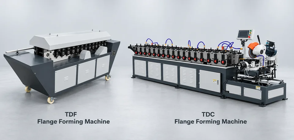
TDF vs TDC: Quick Comparison
| What to check | TDF system | TDC system |
|---|---|---|
| Flange profile | Integrated panel-edge flange in the listed TDF reference | Separate strip profile in the listed LT-series reference |
| Corners and cleats | Use profile-matched parts | Use profile-matched parts |
| Sealing | Verify gasket and assembly | Verify gasket and assembly |
| Forming equipment | Check panel grade, thickness and flange tooling | Check strip width, grade, thickness and section tooling |
Names can vary by market. Match the actual profile and components.
What Is a TDF Flange?
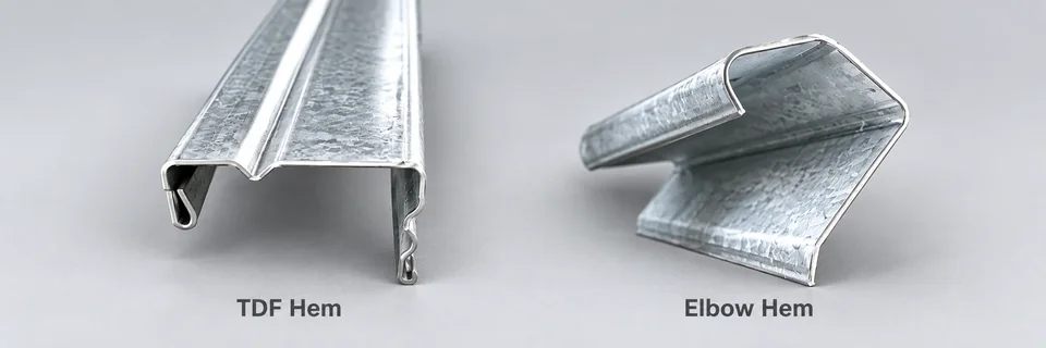
The listed TDF machine forms an integrated flange along the rectangular duct panel edge. Confirm the section geometry and matching components before production.
What Is a TDC Flange?
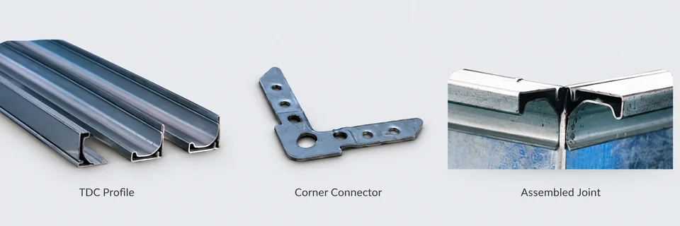
The listed TDC LT-series forms separate strip into a transverse connection profile. Match the drawing, strip width and mating components before ordering.
Key Differences to Check
Profile & component fit
Compare the TDF and TDC drawings, and check sample fit with corners and cleats.
Joint sealing & strength
Review the full joint assembly, including gasket and components, and confirm it meets your project specification.
Cost & production workflow
Compare machine setup, tooling and consumables for your required profile, material range and production volume.
Which System Should You Choose?
- Follow the project specification
- Match your existing corners and cleats
- Test a formed sample before production
Explore Flange Forming Machines
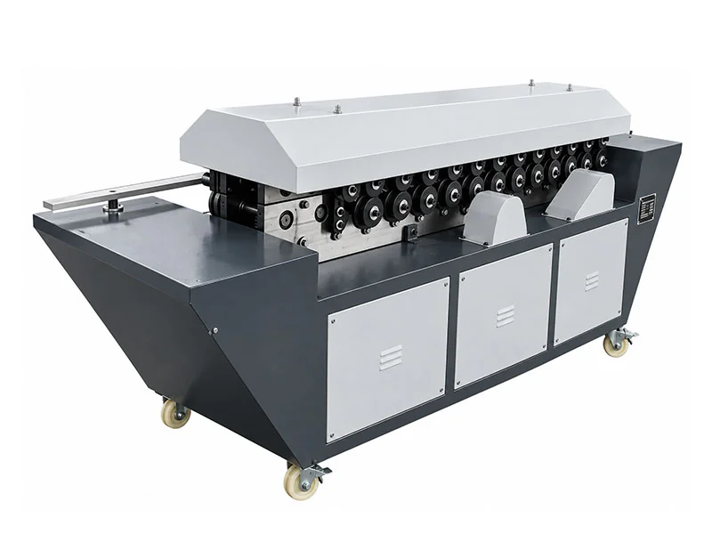
TDF Flange Forming Machine
Confirm your profile, material and production needs.
View Machine Details — TDF flange forming machine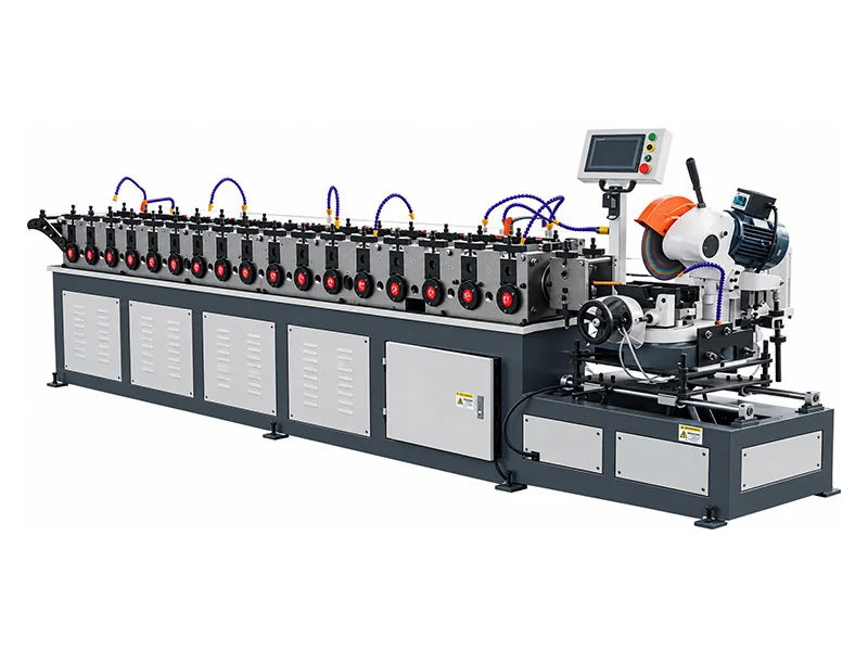
TDC Flange Forming Machine
Confirm your profile, material and production needs.
View Machine Details — TDC flange forming machineCompare the actual fabrication methods
The TDF product reference forms an integrated flange along the duct panel edge. The listed TDC LT-series feeds prepared strip through rollers to make a separate profile. This difference affects stock preparation, tooling and assembly planning.
TDF/TDC names vary across markets. Identify the required section drawing, corner and cleat system before selecting equipment; do not order a profile only by its acronym. A forming-machine name does not establish an approved joint design or project pressure rating.
Published model data for the purchasing decision
The TDF reference lists T-12 for 0.5–1.2 mm galvanized sheet and T-15 for 0.8–1.5 mm galvanized or 0.4–1.0 mm stainless. Both list 35 ± 0.5 mm flange height, with 3 and 4 kW motor references respectively. Confirm the exact grade and requested profile in the order.
The TDC LT30A row lists 118 mm strip width, 1.0 mm sheet thickness, 2000 kg weight and 4650×1020×1380 mm dimensions. LT30B instead lists 123 mm strip width and 2100 kg. A/B names alone do not establish profile interchangeability. The table's paired power values also need clarification in the quotation.
Cost and application checks beyond the machine price
New rectangular duct production
Map panel-edge forming versus separate-strip preparation, then include matching corners, cleats, gaskets and assembly work. Check whether existing duct line functions already support the required profile.
Expansion of an existing workshop
Use an existing acceptable joint and component set as the reference. A new flange that looks similar may not fit stocked corners or cleats. Compare total consumables, changeovers and assembly effort with the same duct order mix.
Sample acceptance before production
- Approve the actual flange section and material.
- Form samples using the quoted tooling.
- Check dimensions and fit with the intended corners and cleats.
- Assemble two representative duct ends with specified sealing components.
- Inspect joint fit and complete any project-required test.
WinYing Machinery reviews profiles and production requirements before discussing configuration. Send the section drawing, mating components and material range. Link the selection to the complete production solution and manufacturing route.
| Item | TDF reference | TDC reference |
|---|---|---|
| Stock route | Duct panel edge | Prepared separate strip |
| Example model | T-12 / T-15 | LT30A / LT30B |
| Dimensions to verify | 35 ± 0.5 mm reference flange height | 118 / 123 mm strip width in these rows |
| Material capacity | Published grade-specific TDF ranges | Confirm material for stated thickness |
| Assembly | Profile-matched corners/cleats/sealing | Profile-matched corners/cleats/sealing |
Frequently Asked Questions
Can TDF and TDC corners be interchanged?
Check the actual profile and test component fit. Do not assume compatibility from the name alone.
Which flange system provides a better seal?
Sealing depends on the complete joint, including the gasket, corner fit, cleats and assembly. Confirm the required performance against your project specification.
What information is needed to select a machine?
Provide the flange drawing or sample, material grade, sheet thickness, working width, power standard and required production output.
Does a TDF machine make the listed TDC profile?
The product references use different forming routes and tooling. Confirm the actual section drawing and machine capability; do not assume interchangeability.
Does a flange machine guarantee duct pressure performance?
No. The completed joint, sealing, reinforcement and project testing determine acceptance.