
TDC Flange Forming Machine
Roll-form prepared strip into the specified TDC profile. Match the LT-series row to strip width and joint components.
- Model groups
- LT20–LT40 A / B
- Strip references
- 86–151 mm
- Thickness references
- 0.8–1.2 mm
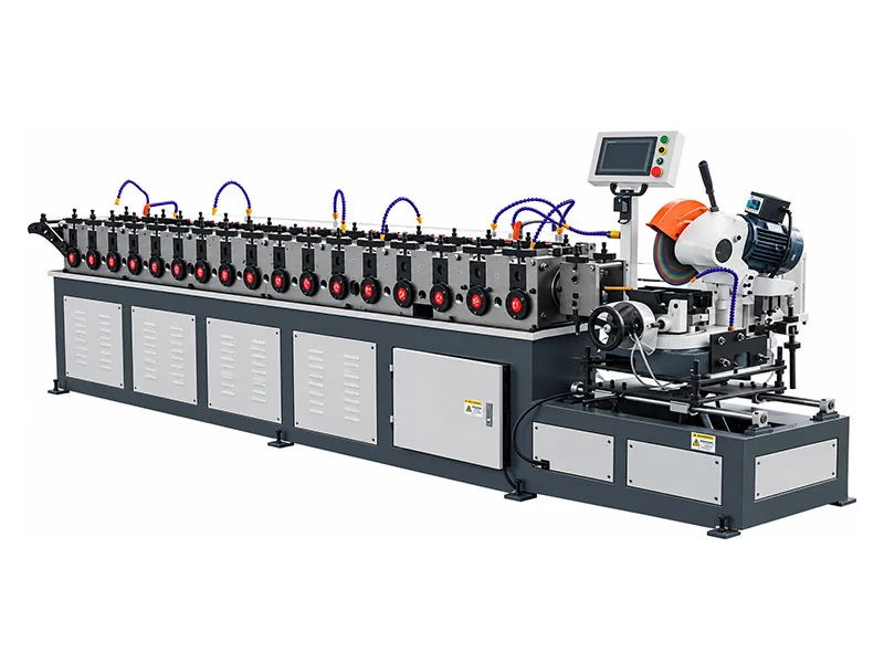
Strip preparation is part of TDC selection
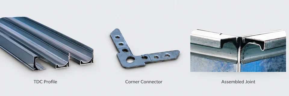
Order the section, not just an LT number
Send the profile drawing and intended corner/component set. Confirm required strip width and sheet material for that section.
The A and B groups have different listed strip widths. Their labels alone do not prove interchangeable tooling or mating fit.
Separate the A and B reference ranges
A-series strip references
The supplied rows list widths from 86 to 146 mm. Check the required LT20A–LT40A row rather than selecting by an overall range.
B-series strip references
The supplied rows list widths from 90 to 151 mm. Compare the exact section drawing and matching components for the selected B row.
Complete LT-Series Supplied Tables
| Model | Strip Width (mm) | Sheet Thickness (mm) | Power (kW) | Weight (kg) | Dimensions (L×W×H) mm |
|---|---|---|---|---|---|
| LT20A | 86 | 0.8 | 3 / 2.4 | 1800 | 4650 × 1020 × 1380 |
| LT25A | 96 | 0.8 | 3 / 2.4 | 1900 | 4650 × 1020 × 1380 |
| LT30A | 118 | 1.0 | 3 / 2.4 | 2000 | 4650 × 1020 × 1380 |
| LT35A | 128 | 1.0 | 4 / 2.4 | 2100 | 4900 × 1020 × 1380 |
| LT40A | 146 | 1.2 | 4 / 2.4 | 2200 | 4900 × 1020 × 1380 |
| Model | Strip Width (mm) | Sheet Thickness (mm) | Power (kW) | Weight (kg) | Dimensions (L×W×H) mm |
|---|---|---|---|---|---|
| LT20B | 90 | 0.8 | 3 / 2.4 | 2000 | 5100 × 1020 × 1380 |
| LT25B | 99 | 0.8 | 3 / 2.4 | 2100 | 5100 × 1020 × 1380 |
| LT30B | 123 | 1.0 | 3 / 2.4 | 2200 | 5100 × 1020 × 1380 |
| LT35B | 132 | 1.0 | 4 / 2.4 | 2300 | 5400 × 1020 × 1380 |
| LT40B | 151 | 1.2 | 4 / 2.4 | 2400 | 5400 × 1020 × 1380 |
Keep the original paired power entries (such as 3 / 2.4 kW) as supplied. Confirm their motor/system definitions, grade basis and final configuration; do not add the numbers into an unverified total.
Approve a formed strip with the actual joint parts
- 01
Specify section
Provide drawing and component set.
- 02
Prepare strip
Use the confirmed row width and material.
- 03
Form sample
Check geometry and material condition.
- 04
Assemble joint
Test mating fit and specified sealing.
Questions to settle before ordering
Do A and B use the same strip width?
No. Use the exact supplied model row and profile drawing.
Can corners be selected by the TDC name alone?
No. Check the actual section and test component fit.
What do paired power values mean?
The supplied table lists paired entries; confirm their definitions in the quotation.
Does the maximum thickness apply to every LT model?
No. Read each model row and confirm material grade.
What should I send?
Section drawing, matching parts, grade, thickness, strip width and utilities.
Tell Us Your TDC Flange Requirements
Send the required profile, strip width, material and thickness so we can confirm the suitable machine model.