
Duct Thickness & Gauge: What to Specify
Published · Updated
Replace an ambiguous gauge label with the actual material and thickness range. Then find the capacity limits across forming, folding and closing before purchasing a machine package.
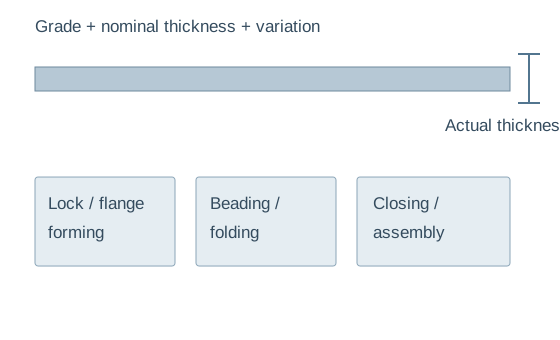
Three materials, three separate confirmations
Galvanized steel
Specify grade, coating and thickness variation from the stock supplier. Check profile dimensions and coating condition on a formed sample.
Use the galvanized range where the product gives one; do not transfer it to another material.
Stainless steel
Specify grade, surface condition and the full thickness range. Its capacity must be separately confirmed for tooling and machine configuration.
TDF T-15 itself lists a different stainless range from its galvanized range.
Aluminum
Include alloy/temper where available and the finished surface requirement. A generic metal thickness rating is insufficient.
Ask for actual material approval rather than assigning the galvanized maximum to aluminum.
The published ranges do not line up automatically
| Model | Listed range | Additional limit |
|---|---|---|
| SA-12HB | 0.5–1.2 mm | Confirm grade/profile |
| T-12 | 0.5–1.2 mm galvanized | Confirm flange components |
| T-15 | 0.8–1.5 mm galvanized; 0.4–1.0 mm stainless | Material-specific |
| G-1.2×2000 | 0.4–1.2 mm | 2000 mm sheet width |
| SL-12 | 0.4–1.5 mm | 1000–1550 mm processing length |
Scroll the comparison table horizontally to see every column.
The SA-12HB reference lists 0.5–1.2 mm. The TDF T-15 lists 0.8–1.5 mm galvanized sheet and 0.4–1.0 mm stainless steel. These differences show why a headline maximum cannot define a complete workshop package.
Check working width and part length alongside thickness. The wider G-1.2×2000 beader has a different range from the G-1.5×1300. Obtain material-specific confirmation for every station and the required profile.
Build the material matrix before requesting a quote
What your stock specification should contain
Gauge designations depend on the material and applicable sheet standard. Obtain nominal thickness, permitted variation and material data from the sheet supplier; state millimeters or inches in the equipment inquiry. Avoid converting a gauge label with an unrelated material chart.
Separate galvanized steel, stainless steel and aluminum. Strength, temper and coating condition affect forming, so a rating for one material is not automatically valid for another. Include the minimum thickness as well as the maximum.
What your duct drawing should contain
Record panel width, section dimensions, length, bead layout, seam profile, transverse connection and reinforcement. These define the operations the sheet must survive.
Include the thinnest recurring order and strongest/thickest material. Check a proposed substitute separately rather than quietly expanding a nominal range.
Two common procurement traps
Maximum-only selection
A machine rated for the thickest sheet may not cover the minimum. For example, the TDF T-15 galvanized reference begins at 0.8 mm; a job below that must be reviewed rather than assumed to work because it is thinner.
Width-only selection
A wider beader can have a lower thickness limit: G-1.2×2000 lists 0.4–1.2 mm, while G-1.5×1300 lists 0.4–1.5 mm. Name the model and the full blank dimensions when confirming capacity.
Construction approval and machine approval are separate
Duct sheet thickness and reinforcement come from the approved project specification. Machine capacity does not determine acceptable duct construction. Beads or a stronger flange do not by themselves authorize reducing sheet thickness.
For commercial HVAC panels, map thickness to dimensions, seams and transverse connections. For industrial ventilation, also specify finish and grade requirements. Review reinforcement planning with the construction drawing rather than treating it as a standalone machine feature.
Acceptance at the thin and thick ends
- List each grade and minimum/maximum thickness.
- Map cutting, beading, lock/flange forming, folding and closing to that range.
- Identify gaps and confirm tooling or alternative configurations.
- Run representative sheets at both thickness limits.
- Inspect profiles, cracking, coating condition, mating fit and closure against agreed criteria.
Keep an approved formed sample and setup record for each material family. When a later coil batch behaves differently, compare stock data and measured thickness before changing the machine setup.
Send a grade-by-thickness matrix
WinYing Machinery reviews the actual material and workpiece before discussing configurations. Ask for a written capacity confirmation at each station, not a package rated only by gauge.
Discuss this application →- 01Grade and permitted variation
- 02Minimum / maximum actual thickness
- 03Panel sizes, seam and flange drawings
- 04Approved samples and acceptance criteria
Frequently Asked Questions
Can I specify only 18 gauge?
Also provide actual thickness and material standard. Gauge designations alone can be ambiguous.
Can galvanized capacity be used for stainless?
Only after confirmation for the actual grade and configuration. Published TDF ranges differ by material.
Does machinery capacity decide duct thickness?
No. Select machinery after the construction requirements have been established.
Why test the minimum thickness?
Thin sheet also needs stable feeding and suitable profile fit. A maximum rating does not establish the whole usable range.