How to Choose an Auto Duct Line
Published · Updated
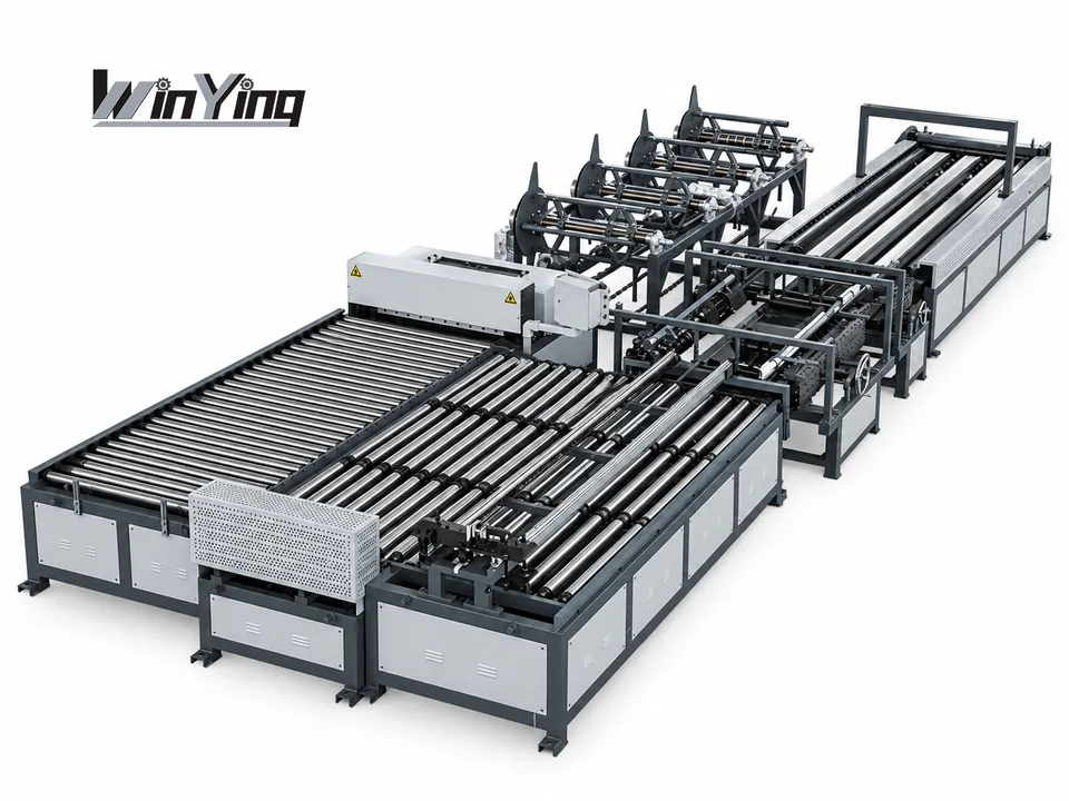
Choose a configuration around the duct you make, the processes you need and the output your workshop requires.
Compare material capacity, connection profiles, automated functions and factory layout before finalizing the line.
Six Checks Before You Choose
Define the finished duct
Specify typical and maximum duct dimensions, the material grade and the complete thickness range.
Check: Confirm working width and material capacity.
Match the connection profiles
Provide the longitudinal seam and transverse flange drawings, including any TDF, TDC or other connection requirements.
Check: Confirm the exact roller sets and connection components.
Choose what to automate
Map feeding, leveling, beading, notching, cutting, edge forming and folding against the proposed line configuration.
Check: Identify which operations remain on separate machines.
Plan realistic output
Describe your job mix, batch sizes, shifts and target output. Include coil changes, handling and downstream seam closing.
Check: Assess the complete workflow, rather than feed speed alone.
Check coil and workshop needs
Confirm coil width, weight and bore size, loading method, installation area and material flow.
Check: Include service access and loading clearance in the layout.
Confirm installation and support
Check power supply, any compressed-air requirements, commissioning, operator training, spare parts and documentation.
Check: Agree the supply scope and acceptance checks.
Compare Configurations by the Work They Do
| Process group | What to confirm in the quotation | What to plan downstream |
|---|---|---|
| Coil preparation | Coil stations, loading capacity, feeding and leveling | Coil storage, lifting method and changeover space |
| Blank processing | Beading, notch patterns, cutting and any punching options | Blank handling and any operations outside the line scope |
| Edge forming | Specified lock and flange profiles, tooling and supported materials | Separate lock or flange machines where not included |
| Folding | Included folding functions and supported duct shapes and sizes | Separate folding equipment where required |
| Assembly & finishing | Whether seam closing or other finishing is included | Assembly, connection components, reinforcement and inspection |
Line 1–6 names group configurations. Confirm each included function from the actual process flow, specification and supply scope.
Match Automation to Your Workshop
Keep separate stations where useful
Compare a blank-processing line with your existing lock, flange and folding equipment. Check operator handling and how prepared blanks move between stations.
Useful comparison inputs: job variety, existing equipment, staffing and available space.
Integrate the required operations
Compare a line with additional forming or folding against the work it removes from separate stations. Verify the profiles, dimensions and output your jobs require.
Useful comparison inputs: repeat batches, transfers, changeovers and downstream capacity.
Prepare These Details for a Quotation
- 01Material: grade and minimum / maximum sheet thickness.
- 02Duct dimensions: typical sizes and maximum required dimensions.
- 03Profiles: longitudinal seam and transverse flange drawings or samples.
- 04Coils: width, weight, bore size and number of material changes.
- 05Production: job mix, batch sizes, shifts and expected output.
- 06Workshop: floor plan, power standard and existing downstream machines.
Explore Auto Duct Line Configurations
Auto Duct Line 3
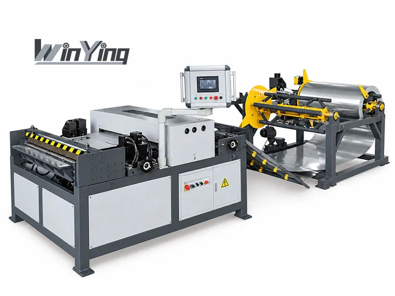
Review the model specification and compare its functions with your production requirements.
View Line 3 Details →Auto Duct Line 6
Review the process configuration, installation layout and equipment included in the supply scope.
View Line 6 Details →Use the listed data as a reference, not a model-number promise
The current Line 1–6 detail pages repeat the same YSDCNC-V-1250/V-1500 reference table. They do not establish six distinct process packages. Ask for the selected model's actual configuration sheet, machine list and process diagram before assigning functions to a line number.
That shared table lists 0.4–1.5 mm thickness, 1250/1500 mm widths, 15 m/min maximum working speed and 30 kW power. It also lists a coiler reference of 4×7000 kg and different layout dimensions. Confirm material basis, actual coil stations and loading arrangement in the specific order.
Published footprint and speed need context
The reference table gives 14×5×1.5 m for V-1250 and 14×5.5×1.5 m for V-1500. These are equipment references, not the complete usable workshop space. Add coil storage/loading, access, transfers and downstream assembly to the layout.
Maximum feed or working speed does not establish finished ducts per hour. Coil changes, notch/cut cycles, edge forming, folding, closing and order changes must be included. Ask for a trial using your job mix and operators.
A supply-scope table prevents missing operations
For each stage, mark included equipment, separately supplied equipment and existing equipment. Confirm actual lock and flange profiles, minimum dimensions, tooling changes and control functions. Review the flange route alongside the manufacturing process.
Check coil bore, width and weight, lifting arrangements, power, compressed air and foundation needs. Obtain commissioning, training, manuals, service access and spare-parts information for the selected line.
Agree acceptance on completed orders
- Approve grade, thickness limits, profiles and duct dimensions.
- Demonstrate a material/coil change and representative size changes.
- Produce blanks and formed parts through every included operation.
- Complete remaining closing/assembly and inspect finished ducts.
- Record accepted output with the actual staffing and downstream route.
WinYing Machinery discusses OEM/configuration requirements from the application. Send the workshop plan, coil data and order mix for the full production solution. Ask the quotation to distinguish reference figures from the confirmed purchased configuration.
| Reference item | V-1250 | V-1500 |
|---|---|---|
| Width | 1250 mm | 1500 mm |
| Thickness reference | 0.4–1.5 mm | 0.4–1.5 mm |
| Maximum working speed | 15 m/min | 15 m/min |
| Power | 30 kW | 30 kW |
| Equipment dimensions | 14×5×1.5 m | 14×5.5×1.5 m |
Frequently Asked Questions
Should I choose the highest line number?
Choose by the actual process flow, material capacity, required profiles and workshop needs. Model names alone do not confirm the complete equipment scope.
Will an automatic line replace every separate machine?
That depends on the quoted configuration. Confirm which forming, folding, seam-closing and finishing operations still require downstream equipment.
How should I compare production output?
Use representative jobs and include batch sizes, coil changes, handling and downstream operations. Agree how output will be demonstrated for your material and duct sizes.
What should I confirm before ordering?
Confirm the written specification, process flow, tooling, layout, utilities, delivery scope, commissioning, training, support and acceptance checks.
Do Line 1–6 pages establish six distinct packages?
Their current detail pages repeat one reference table. Obtain the selected line's actual process diagram, equipment list and configuration sheet.