
CNC vs Hydraulic Press Brake? Compare the Functions
Published · Updated
A CNC press brake can be hydraulic. The useful decision is which programmable movements and setup functions your parts need, while force, tooling and clearance are still checked separately.
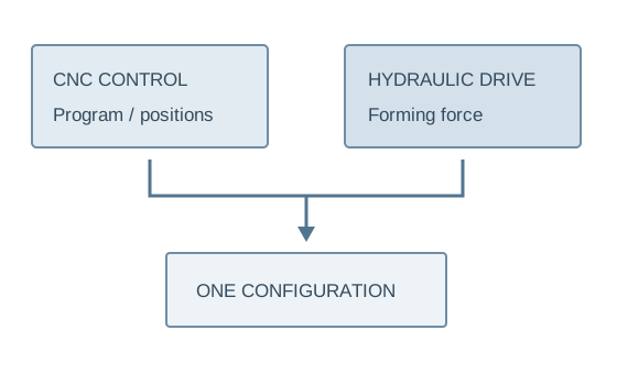
Separate the three layers of a machine proposal
Layer 1 · forming capacity
Grade, thickness, full bend length and tooling determine the force question. Open height, stroke, throat and return clearance determine whether the workpiece fits.
Layer 2 · positioning and sequence
Ask which positions and movements are programmed, which axes are controlled and how the part is gauged through its sequence. CNC does not mean every axis or option is included.
The practical comparison is simpler control versus more programming
The practical comparison is usually a simpler controlled hydraulic press brake versus a hydraulic press brake with more programmable functions. The CNC product reference explicitly describes hydraulic drive with configurable programming, backgauge and tooling.
Do not assume the 'hydraulic' machine lacks every positioning function or that 'CNC' includes every axis. Request an axis list, control specification and exact supply scope for each quotation.
| Item | Simpler controlled configuration | CNC configuration |
|---|---|---|
| Setup | Confirm manual/positioned functions | Confirm program and axis scope |
| Repeat parts | Operator settings and procedures | Program reuse where supported |
| Multiple bends | Handling and sequence planning | Programmed sequence where supported |
| Force capacity | Material/tooling review still required | Material/tooling review still required |
| Acceptance | Completed representative parts | Completed parts plus program recall |
Scroll the comparison table horizontally to see every column.
Where reusable programs solve a real production problem
Recurring multi-bend parts
Demonstrate creation, recall and restart of the part program. Check gauge movements and the final dimensions after all bends. Program reuse is useful when the same parts return and their setup is costly.
Occasional simple bends
Compare actual setup and operator effort for the smaller job mix. Extra functions should address useful work rather than replace a clear tooling and positioning procedure with a longer feature list.
Recurring parts with several bends, repeated gauge positions and programs reused across batches can benefit from programmable setup. For occasional simple bends, assess whether those functions save enough setup and operator effort to justify the configuration.
CNC does not remove material variation, springback, tooling wear or clearance constraints. Part drawings, material data, tooling and inspection remain essential. Offline programming, angle measurement and automatic compensation must each be confirmed if required; the control label alone does not promise them.
A reference model gives dimensions—not a universal part rating
HTC 100T3200 published row
1000 kN · 3200 mm
Nominal pressure and bending length; the row also lists 120 mm stroke, 320 mm throat and 380 mm open height. Review the complete HTC table.
CNC reference configuration
The CNC reference describes hydraulic drive and configurable programming, backgauge and tooling. It does not specify every axis, angle-measuring function or offline option.
Request those functions individually if the part set needs them.
Capacity at the required bend and access to the final return still need confirmation. Controller positioning values do not automatically become the tolerance of the completed part.
Run the same part set on the two proposals
- 01Approve tools
Agree the bend method, tooling and sequence.
- 02Create setup
Demonstrate the required control/positioning functions.
- 03Repeat batch
Include program recall or repeated operator settings.
- 04Finish part
Complete all bends and check access/removal.
- 05Inspect output
Measure the agreed final angles and dimensions.
Include the material changes and tool changes in your ordinary production. Material variation, springback and tooling condition remain process variables at either control level.
Make training and support part of the control choice
Operator setup
Confirm how programs/settings are created, adjusted, backed up and recalled on the actual controller.
Tooling scope
List the included tools and the parts/radii they cover. CNC cannot compensate for an unsuitable or overloaded tool.
Service and documentation
Confirm manuals, training, support and replacement information for the supplied configuration. Keep the accepted setup and part samples.
Ask for the functions your repeat parts use
WinYing Machinery can review the drawing set and recurring batches before discussing control scope. Compare a simpler and a CNC proposal against the same work and acceptance rules.
Discuss this application →- 01Representative drawings and materials
- 02Full bend length, return geometry and radii
- 03Program reuse and positioning requirements
- 04Tools, training and completed-part tolerances
Frequently Asked Questions
Is CNC hydraulic?
It can be. The current CNC reference describes hydraulic drive; CNC concerns control.
Does CNC guarantee angle accuracy?
No universal finished tolerance follows from the label. Agree a representative part trial and inspection.
Are all axes included?
Confirm the axis list and control functions in the quotation.
When does CNC add value?
Evaluate repeat programs, multiple bends and setup savings for your actual jobs.