Auto Duct Line 4
Explore our Auto Duct Line 4 for seam and flange planning. Seam and flange requirements govern the tooling and later assembly work.
Duct seam and flange preparation starts with the longitudinal joint and transverse connection drawings. Confirm which tools and finishing operations are included in Line 4.
The Auto Duct Line 4 price depends on required seam and flange profiles, forming tools, material capacity and included modules. For a China supplier quotation, give WinYing the connection drawings and confirm the manufacturer, factory supply terms and which assembly operations require separate equipment. Compare related options: Auto Duct Production Lines.
- Shared width
- 1250 / 1500 mm
- Shared sheet range
- 0.4–1.5 mm
- Package
- Quote-specific
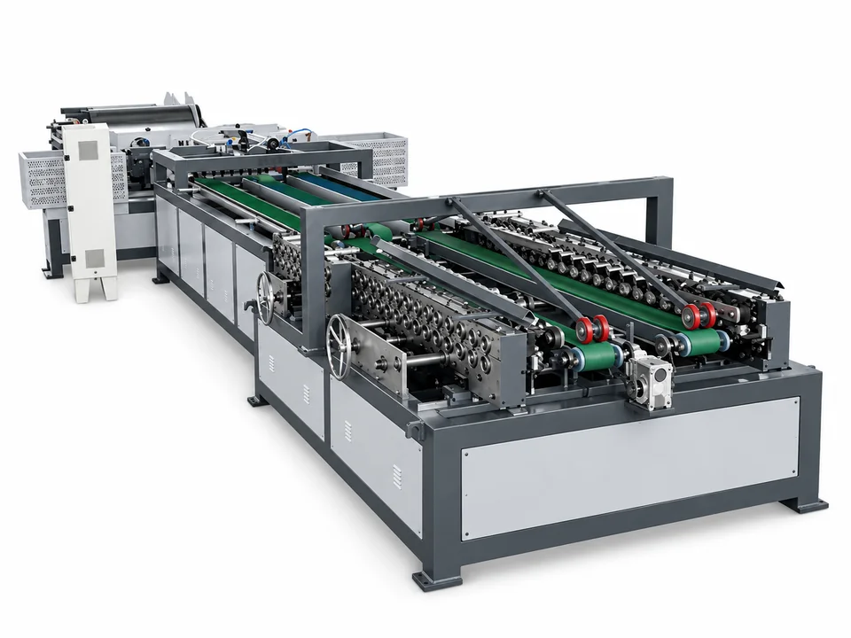
Line 4: Joint and Flange Process Planning
Buyers evaluating rectangular duct production line, HVAC duct manufacturing machine, air duct fabrication line should check the actual process scope before ordering. For Auto Duct Line 4, first identify the rectangular duct joint and flange system required by the project. TDF, TDC and other connections may involve different forming and assembly equipment. Verify which steps are integrated into the quoted line and which remain separate before comparing configurations. For a broader comparison, see how to choose an automatic duct line and all six line configurations.
Choose the duct joint route
Seam and flange requirements govern the tooling and later assembly work.
The joint drawing is the reference
Provide longitudinal seam and transverse flange details. A duct line name does not guarantee Pittsburgh, TDF or TDC tooling is included.
| Requirement | Confirmation |
|---|---|
| Longitudinal seam | Required profile and mating edge; included tooling. |
| Transverse flange | Integral or separate-strip route and component fit. |
| Folding and closing | Included operations and separate downstream work. |
| Assembly sample | Finished dimensions and accepted joint condition. |
Shared YSDCNC Reference Data
| Parameter | YSDCNC-V-1250 | YSDCNC-V-1500 |
|---|---|---|
| Material Thickness | 0.4–1.5 mm | 0.4–1.5 mm |
| Max. Width | 1250 mm | 1500 mm |
| Max. Working Speed | 15 m/min | 15 m/min |
| Max. Weight of Coiler | 4 × 7000 kg | 4 × 7000 kg |
| Power | 30 kW | 30 kW |
| Machine Weight | 13,500 kg | 14,500 kg |
| Dimensions (L × W × H) | 14 × 5 × 1.5 m | 14 × 5.5 × 1.5 m |
The YSDCNC V1250/V1500 figures are reference data. Confirm the selected line’s equipment list, operations, layout and final specifications in the quotation.
Questions to settle before ordering
Does the line number establish all included operations?
No. Confirm the equipment list and tooling in the quotation.
Do these reference specifications apply to every configuration?
The YSDCNC V1250/V1500 figures are reference data. Confirm the selected line’s equipment list, operations, layout and final specifications in the quotation.
Can the listed speed define completed duct output?
No. Include setup, changes, transfer and downstream operations.
Can it match existing workshop machines?
Provide working ranges, panel drawings and joint details for interface review.
What should I send WinYing?
Material, thickness, duct drawings, batch mix, existing machines and site utilities.
Need an Automatic Duct Production Line?
Tell us your material, sheet thickness, duct size and production requirements. We will review the application and respond with suitable equipment information.